Understanding What We Built
Deep dive into the scaffold. System takeover. Copper lists. Hardware sprites. VBlank.
What You’re Building
Understanding.
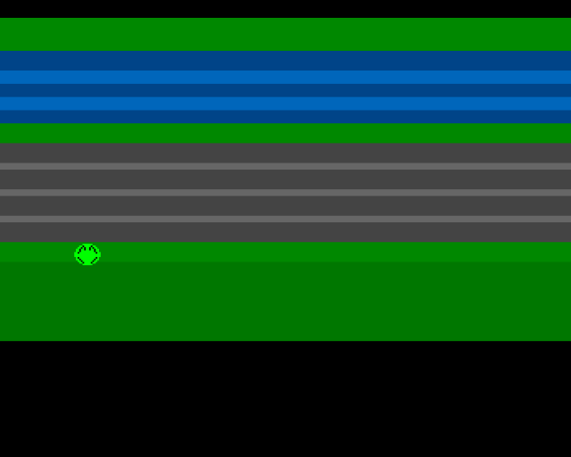
This unit produces the same output as Unit 2. No new features. Instead, we stop and understand everything we’ve built. The code is heavily commented—read it alongside this explanation.
By the end of this unit:
- You understand why we take over the system
- You know how Copper lists create the display
- You know how hardware sprites work
- You understand VBlank timing
Why Theory Matters
We could keep adding features. Movement works, the display looks good. But programming without understanding is fragile. One wrong register, one misunderstood concept, and you’re staring at a blank screen with no idea why.
This unit builds the foundation for everything that follows.
Taking Over the Machine
The first thing our code does is disable the operating system:
```asm move.w #$7fff,INTENA(a5) ; Disable all interrupts move.w #$7fff,INTREQ(a5) ; Clear pending interrupts move.w #$7fff,DMACON(a5) ; Disable all DMA ```
Why Take Over?
AmigaOS is a preemptive multitasking operating system. It runs multiple programs simultaneously by rapidly switching between them using interrupts.
For a game, this creates problems:
- Timing uncertainty: The OS might interrupt your code at any moment
- Resource conflicts: The OS might be using DMA you need
- Overhead: The OS consumes CPU time and memory
By disabling interrupts and DMA, we get predictable timing and full hardware access.
The Magic Number $7FFF
Amiga control registers use bit 15 as a SET/CLR flag:
- Bit 15 = 0: Clear the bits that are 1 in bits 0-14
- Bit 15 = 1: Set the bits that are 1 in bits 0-14
So `$7fff` means “clear all of bits 0-14”. Later, `$83a0` enables only what we need.
The Custom Chipset
Agnus (Address Generator)
Contains the Copper and Blitter. Manages all DMA operations.
Denise (Display Encoder)
Creates the video signal—sprites, bitplanes, colours.
Paula (Ports and Audio)
Four channels of 8-bit audio, floppy disk, serial/parallel ports.
The Copper
A simple co-processor that runs synchronised to the video beam. It can only:
- WAIT for a specific screen position
- MOVE a value to a hardware register
Our playfield is just colour changes:
```asm dc.w $2c07,$fffe ; WAIT for line 44 dc.w COLOR00,COLOUR_HOME ; MOVE green to colour 0
dc.w $4007,$fffe ; WAIT for line 64 dc.w COLOR00,COLOUR_WATER ; MOVE blue to colour 0 ```
No bitmap. Just the Copper changing one colour register as the beam scans down.
Copper Instruction Format
WAIT: `$VVHH,$FFFE` (VV=vertical, HH=horizontal) MOVE: `$XXYY,$VVVV` (XX=register/2, VVVV=value)
Hardware Sprites
The Amiga has 8 hardware sprites. Each is 16 pixels wide.
Without hardware sprites, moving an object means erasing and redrawing 50 times per second. With sprites, just write new coordinates—the chipset handles the rest.
Sprite Data Format
```asm frog_data: dc.w $b450,$c400 ; Control words (Y, X positions) dc.w $0000,$0000 ; Line 1 (plane0, plane1) dc.w $07e0,$0000 ; Line 2 ; … more lines … dc.w $0000,$0000 ; End marker ```
Two bitplanes give 4 colours: transparent, colour 17, colour 18, colour 19.
Vertical Blank
The video beam scans 50 times per second (PAL). Vertical blank is when the beam returns to the top.
Update graphics during VBlank to avoid tearing (old and new frames mixed together).
```asm wait_vblank: move.l #$1ff00,d1 .wait: move.l VPOSR(a5),d0 and.l d1,d0 bne.s .wait rts ```
Joystick Decoding
The Amiga uses quadrature encoding from Atari hardware:
```asm move.w JOY1DAT(a5),d0 ; Read raw move.w d0,d1 lsr.w #1,d1 ; Shift copy eor.w d1,d0 ; XOR decodes it ```
After decoding: Bit 8=Up, Bit 0=Down, Bit 9=Left, Bit 1=Right.
The DMACON Mystery
We enable DMA with `$83a0`:
- Bit 15: SET (enable)
- Bit 9: DMAEN (master)
- Bit 8: BPLEN (bitplane)
- Bit 7: COPEN (Copper)
- Bit 5: SPREN (sprite)
Why BPLEN with no bitplanes? Hardware quirk: sprites don’t render without BPLEN enabled.
Key Takeaways
- System takeover gives predictable timing
- The Copper changes registers in sync with the beam
- Hardware sprites are drawn automatically
- VBlank is when we safely update graphics
- BPLEN must be enabled for sprites (hardware quirk)
- $7fff disables; $8xxx enables
The Code
;══════════════════════════════════════════════════════════════════════════════
; SIGNAL - A Frogger-style game for the Commodore Amiga
; Unit 3: Understanding What We Built
;
; This is the same code as Unit 2, with extensive comments explaining
; every aspect of how the Amiga's custom chipset creates our game display.
;══════════════════════════════════════════════════════════════════════════════

;══════════════════════════════════════════════════════════════════════════════
; TWEAKABLE VALUES
;══════════════════════════════════════════════════════════════════════════════
; These constants let you experiment without understanding the code.
; Change them, rebuild, see results.

FROG_START_X    equ 160         ; Horizontal: 0=left edge, 320=right edge
FROG_START_Y    equ 180         ; Vertical: 0=top, 256=bottom (PAL)

MOVE_SPEED      equ 2           ; Pixels moved per frame (at 50fps PAL)

; Screen boundaries for the frog
MIN_X           equ 48          ; Sprites can't go left of ~44
MAX_X           equ 280         ; Or right of ~304
MIN_Y           equ 44          ; Top of playfield (home zone)
MAX_Y           equ 196         ; Bottom of playfield (start zone)

FROG_HEIGHT     equ 16          ; Sprite is 16 pixels tall

; Colours in $0RGB format (0-15 for each component)
; Example: $0F00 = red, $00F0 = green, $000F = blue, $0FFF = white
COLOUR_HOME     equ $0080       ; Home zone: dark green
COLOUR_WATER    equ $0048       ; Water: dark blue
COLOUR_WAVE     equ $006b       ; Water highlight: lighter blue
COLOUR_MEDIAN   equ $0080       ; Safe median: dark green
COLOUR_ROAD     equ $0444       ; Road: dark grey
COLOUR_MARKER   equ $0666       ; Lane markings: lighter grey
COLOUR_START    equ $0080       ; Start zone: dark green
COLOUR_BORDER   equ $0070       ; Border: slightly different green

; Sprite palette (colours 17-19 in the Amiga palette)
; Sprites use a separate palette from the playfield
COLOUR_FROG     equ $00f0       ; Bright green body
COLOUR_EYES     equ $0ff0       ; Yellow eyes
COLOUR_OUTLINE  equ $0000       ; Black outline

;══════════════════════════════════════════════════════════════════════════════
; HARDWARE REGISTER DEFINITIONS
;══════════════════════════════════════════════════════════════════════════════
; The Amiga's custom chipset is memory-mapped starting at $DFF000.
; Each register is accessed as an offset from this base address.

CUSTOM      equ $dff000         ; Custom chip base address

; DMA and interrupt control
DMACONR     equ $002            ; DMA control read (tells us what's enabled)
DMACON      equ $096            ; DMA control write (enables/disables DMA channels)
INTENA      equ $09a            ; Interrupt enable (which interrupts are active)
INTREQ      equ $09c            ; Interrupt request (which interrupts are pending)

; Timing
VPOSR       equ $004            ; Vertical beam position (high bits)
                                ; Used with VHPOSR ($006) for full position

; Input
JOY1DAT     equ $00c            ; Joystick port 2 data register

; Copper (display co-processor)
COP1LC      equ $080            ; Copper list 1 location (32-bit address)
COPJMP1     equ $088            ; Copper jump strobe (writing here starts copper)

; Colours
COLOR00     equ $180            ; Background colour (colour 0)
                                ; COLOR01-COLOR31 follow at $182, $184, etc.

; Sprite registers
SPR0PTH     equ $120            ; Sprite 0 pointer high word
SPR0PTL     equ $122            ; Sprite 0 pointer low word
                                ; SPR1PTH/L at $124/$126, and so on up to SPR7

;══════════════════════════════════════════════════════════════════════════════
; CODE SECTION
;══════════════════════════════════════════════════════════════════════════════
; The section directive tells the assembler how to organise the output.
;
; "code_c" means "code in Chip RAM". Chip RAM is the first 512K (or more)
; that the custom chipset can access. The Copper and sprites MUST be in
; Chip RAM - they can't see Fast RAM.
;
; Without "_c", data would go to Fast RAM, which is faster for the CPU
; but invisible to the custom chipset.

            section code,code_c

start:
            lea     CUSTOM,a5           ; A5 = $DFF000 (custom chip base)
                                        ; We keep this in A5 throughout the program
                                        ; for quick access to hardware registers

;──────────────────────────────────────────────────────────────────────────────
; SYSTEM TAKEOVER
;──────────────────────────────────────────────────────────────────────────────
; AmigaOS is a preemptive multitasking operating system. It uses interrupts
; to switch between tasks, and DMA for disk, sound, and graphics.
;
; For a game that needs precise timing and full hardware control, we disable
; all of this. The OS stops running; we own the machine.
;
; This is why you need to reset to exit - there's no OS to return to!

            move.w  #$7fff,INTENA(a5)   ; Disable ALL interrupts
                                        ; $7fff = bits 0-14 set, bit 15 clear
                                        ; Bit 15 is SET/CLR: 0=disable, 1=enable
                                        ; So this disables bits 0-14

            move.w  #$7fff,INTREQ(a5)   ; Clear any pending interrupt requests
                                        ; Even disabled interrupts might be waiting

            move.w  #$7fff,DMACON(a5)   ; Disable ALL DMA channels
                                        ; Same SET/CLR bit 15 logic
                                        ; Stops copper, sprites, bitplanes, audio, disk

;──────────────────────────────────────────────────────────────────────────────
; INITIALISE FROG POSITION
;──────────────────────────────────────────────────────────────────────────────

            move.w  #FROG_START_X,frog_x    ; Set initial X position
            move.w  #FROG_START_Y,frog_y    ; Set initial Y position

;──────────────────────────────────────────────────────────────────────────────
; SET UP SPRITE POINTER
;──────────────────────────────────────────────────────────────────────────────
; The Copper needs to know where sprite data is in memory. We write the
; address of our sprite data into the Copper list.
;
; Amiga addresses are 32-bit, but each Copper instruction is only 32 bits
; total (16-bit register + 16-bit value). So we need TWO instructions:
; one for the high 16 bits, one for the low 16 bits.

            lea     frog_data,a0        ; A0 = address of sprite data
            move.l  a0,d0               ; D0 = same address (32-bit)
            swap    d0                  ; D0 high word now in low word
            lea     sprpth_val,a1       ; A1 = where to write high word
            move.w  d0,(a1)             ; Write high word to Copper list
            swap    d0                  ; Restore: low word back in low word
            lea     sprptl_val,a1       ; A1 = where to write low word
            move.w  d0,(a1)             ; Write low word to Copper list

;──────────────────────────────────────────────────────────────────────────────
; UPDATE SPRITE CONTROL WORDS
;──────────────────────────────────────────────────────────────────────────────

            bsr     update_sprite       ; Set initial sprite position

;──────────────────────────────────────────────────────────────────────────────
; INSTALL COPPER LIST
;──────────────────────────────────────────────────────────────────────────────
; The Copper is a simple processor that runs in sync with the video beam.
; It can WAIT for a specific screen position, or MOVE a value to a register.
; Our Copper list sets colours at specific scanlines to create the playfield.

            lea     copperlist,a0       ; A0 = address of our Copper list
            move.l  a0,COP1LC(a5)       ; Tell hardware where list is
            move.w  d0,COPJMP1(a5)      ; "Strobe" register - writing ANY value
                                        ; here makes the Copper jump to COP1LC

;──────────────────────────────────────────────────────────────────────────────
; ENABLE DMA
;──────────────────────────────────────────────────────────────────────────────
; Now we selectively enable only what we need:
;
; $83a0 = %1000 0011 1010 0000
;         │    │  │ │  │
;         │    │  │ │  └─ Bit 5: SPREN (sprite DMA enable)
;         │    │  │ └──── Bit 7: COPEN (Copper DMA enable)
;         │    │  └────── Bit 8: BPLEN (bitplane DMA enable)
;         │    └───────── Bit 9: DMAEN (master DMA enable)
;         └────────────── Bit 15: SET (1=enable the bits below)
;
; IMPORTANT: We need BPLEN even though we have no bitplanes!
; Without it, sprites don't render correctly. This is a hardware quirk.

            move.w  #$83a0,DMACON(a5)   ; Enable master + copper + sprites + bitplanes

;══════════════════════════════════════════════════════════════════════════════
; MAIN LOOP
;══════════════════════════════════════════════════════════════════════════════
; This runs 50 times per second (PAL) or 60 times per second (NTSC).
; Each iteration:
;   1. Wait for vertical blank (beam at bottom of screen)
;   2. Read joystick input
;   3. Update frog position based on input
;   4. Update sprite control words for new position

mainloop:
            bsr.s   wait_vblank         ; Wait for vertical blank
            bsr.s   read_joystick       ; Read joystick -> D0
            bsr.s   move_frog           ; Move frog based on D0
            bsr     update_sprite       ; Update sprite position

            ; Check left mouse button (active low at $BFE001 bit 6)
            btst    #6,$bfe001          ; Test bit 6 of CIA-A PRA
            bne.s   mainloop            ; If not pressed (bit=1), continue

            ; Button pressed - but we have nowhere to go!
            ; On a real Amiga, you'd restore the system here.
            ; For now, just keep looping until reset.
            bra.s   mainloop

;══════════════════════════════════════════════════════════════════════════════
; SUBROUTINES
;══════════════════════════════════════════════════════════════════════════════

;──────────────────────────────────────────────────────────────────────────────
; WAIT_VBLANK - Wait for vertical blank
;──────────────────────────────────────────────────────────────────────────────
; The video beam scans from top-left to bottom-right, then returns to top.
; "Vertical blank" is when the beam is returning - no visible output.
; This is the safe time to update graphics without visible tearing.
;
; VPOSR contains the beam position. We wait until it's at line 0.

wait_vblank:
            move.l  #$1ff00,d1          ; Mask: bits 16-8 (vertical position)
.wait:
            move.l  VPOSR(a5),d0        ; Read beam position
            and.l   d1,d0               ; Mask out horizontal position
            bne.s   .wait               ; Loop until vertical = 0
            rts

;──────────────────────────────────────────────────────────────────────────────
; READ_JOYSTICK - Read and decode joystick input
;──────────────────────────────────────────────────────────────────────────────
; JOY1DAT contains joystick data, but it's encoded weirdly (inherited from
; the Atari 400/800). The vertical movement affects the horizontal bits
; through XOR, so we need to decode it.
;
; Raw JOY1DAT:
;   Bit 9: Y1 XOR X1 (left signal)
;   Bit 8: Y1 (up signal before decode)
;   Bit 1: Y0 XOR X0 (right signal)
;   Bit 0: Y0 (down signal before decode)
;
; After XOR decoding, bits represent actual directions.

read_joystick:
            move.w  JOY1DAT(a5),d0      ; Read raw joystick data
            move.w  d0,d1               ; Copy to D1
            lsr.w   #1,d1               ; Shift D1 right by 1
            eor.w   d1,d0               ; XOR with shifted copy
                                        ; This decodes the quadrature encoding
            rts
            ; Result in D0:
            ;   Bit 8 = up
            ;   Bit 0 = down
            ;   Bit 9 = left
            ;   Bit 1 = right

;──────────────────────────────────────────────────────────────────────────────
; MOVE_FROG - Update frog position based on joystick
;──────────────────────────────────────────────────────────────────────────────
; For each direction:
;   1. Test if that direction bit is set
;   2. Calculate new position
;   3. Check against boundary
;   4. Store new position if within bounds

move_frog:
            ; --- Check Up (bit 8) ---
            btst    #8,d0               ; Test up bit
            beq.s   .no_up              ; Skip if not pressed
            move.w  frog_y,d1           ; Get current Y
            sub.w   #MOVE_SPEED,d1      ; Subtract (up = decrease Y)
            cmp.w   #MIN_Y,d1           ; Compare with top boundary
            blt.s   .no_up              ; Skip if past boundary
            move.w  d1,frog_y           ; Store new Y
.no_up:
            ; --- Check Down (bit 0) ---
            btst    #0,d0
            beq.s   .no_down
            move.w  frog_y,d1
            add.w   #MOVE_SPEED,d1      ; Add (down = increase Y)
            cmp.w   #MAX_Y,d1
            bgt.s   .no_down            ; Skip if past boundary
            move.w  d1,frog_y
.no_down:
            ; --- Check Left (bit 9) ---
            btst    #9,d0
            beq.s   .no_left
            move.w  frog_x,d1
            sub.w   #MOVE_SPEED,d1      ; Subtract (left = decrease X)
            cmp.w   #MIN_X,d1
            blt.s   .no_left
            move.w  d1,frog_x
.no_left:
            ; --- Check Right (bit 1) ---
            btst    #1,d0
            beq.s   .no_right
            move.w  frog_x,d1
            add.w   #MOVE_SPEED,d1      ; Add (right = increase X)
            cmp.w   #MAX_X,d1
            bgt.s   .no_right
            move.w  d1,frog_x
.no_right:
            rts

;──────────────────────────────────────────────────────────────────────────────
; UPDATE_SPRITE - Write position to sprite control words
;──────────────────────────────────────────────────────────────────────────────
; Hardware sprites have control words at the start of their data:
;
; Word 0: VSTART[7:0] << 8 | HSTART[8:1]
;         (vertical start position, horizontal start / 2)
;
; Word 1: VSTOP[7:0] << 8 | VSTART[8] << 2 | VSTOP[8] << 1 | HSTART[0]
;         (vertical stop position, plus extra bits for large positions)
;
; For our 16-pixel tall sprite starting at Y positions < 256, we can
; simplify: just pack VSTART and HSTART/2 into word 0, VSTOP into word 1.

update_sprite:
            lea     frog_data,a0        ; A0 = sprite data start
            move.w  frog_y,d0           ; D0 = Y position (VSTART)
            move.w  frog_x,d1           ; D1 = X position (HSTART)

            ; Build control word 0: VSTART << 8 | HSTART >> 1
            move.w  d0,d2               ; D2 = VSTART
            lsl.w   #8,d2               ; Shift to high byte
            lsr.w   #1,d1               ; HSTART / 2 (sprites use half-res X)
            or.b    d1,d2               ; Combine into low byte
            move.w  d2,(a0)             ; Write to sprite control word 0

            ; Build control word 1: VSTOP << 8
            add.w   #FROG_HEIGHT,d0     ; D0 = VSTOP (VSTART + height)
            lsl.w   #8,d0               ; Shift to high byte
            move.w  d0,2(a0)            ; Write to sprite control word 1

            rts

;══════════════════════════════════════════════════════════════════════════════
; VARIABLES
;══════════════════════════════════════════════════════════════════════════════
; These are in the code section so they're in Chip RAM with everything else.
; The 68000 can access them with PC-relative addressing for efficiency.

frog_x:     dc.w    160             ; Current horizontal position
frog_y:     dc.w    180             ; Current vertical position

;══════════════════════════════════════════════════════════════════════════════
; COPPER LIST
;══════════════════════════════════════════════════════════════════════════════
; The Copper executes simple instructions synchronised to the video beam.
; Each instruction is 32 bits (two 16-bit words).
;
; MOVE instruction: $XXYY,$VVVV
;   XX = register offset / 2 (bits 8-1 of register address)
;   YY = 00 (identifies this as a MOVE)
;   VVVV = 16-bit value to write
;
; WAIT instruction: $VVHH,$FFFE
;   VV = vertical position to wait for
;   HH = horizontal position to wait for
;   $FFFE = identifies this as a WAIT (bits 0 and 15 clear)
;
; The $07 in our WAITs means "wait for horizontal position 7" which is
; just after the left edge of the visible screen.

copperlist:
            dc.w    COLOR00,$0000       ; MOVE: Set background to black

            ; --- Sprite 0 palette (colours 17-19) ---
            ; Sprites 0-1 share colours 16-19 ($1A0-$1A6)
            ; Colour 16 ($1A0) is transparent, 17-19 are the sprite colours
            dc.w    $01a2,COLOUR_FROG   ; MOVE: Colour 17 = frog body
            dc.w    $01a4,COLOUR_EYES   ; MOVE: Colour 18 = eyes
            dc.w    $01a6,COLOUR_OUTLINE ; MOVE: Colour 19 = outline

            ; --- Sprite 0 pointer ---
            ; These values are filled in by the CPU at startup
            dc.w    SPR0PTH             ; MOVE: SPR0PTH register ($120)
sprpth_val: dc.w    $0000               ; Value: high word of sprite address
            dc.w    SPR0PTL             ; MOVE: SPR0PTL register ($122)
sprptl_val: dc.w    $0000               ; Value: low word of sprite address

            ; === HOME ZONE (line $2C = 44) ===
            dc.w    $2c07,$fffe          ; WAIT for line 44, position 7
            dc.w    COLOR00,COLOUR_HOME  ; MOVE: Background = green

            ; === WATER ZONE (5 lanes with wave highlights) ===
            dc.w    $4007,$fffe          ; WAIT for line 64
            dc.w    COLOR00,COLOUR_WATER ; Dark blue

            dc.w    $4c07,$fffe          ; WAIT for line 76
            dc.w    COLOR00,COLOUR_WAVE  ; Light blue highlight

            dc.w    $5407,$fffe          ; WAIT for line 84
            dc.w    COLOR00,COLOUR_WATER ; Dark blue

            dc.w    $5c07,$fffe          ; WAIT for line 92
            dc.w    COLOR00,COLOUR_WAVE  ; Light blue highlight

            dc.w    $6407,$fffe          ; WAIT for line 100
            dc.w    COLOR00,COLOUR_WATER ; Dark blue

            ; === MEDIAN (safe zone, line $6C = 108) ===
            dc.w    $6c07,$fffe
            dc.w    COLOR00,COLOUR_MEDIAN

            ; === ROAD ZONE (4 lanes with markings) ===
            dc.w    $7807,$fffe          ; Line 120 - road
            dc.w    COLOR00,COLOUR_ROAD

            dc.w    $8407,$fffe          ; Line 132 - marking
            dc.w    COLOR00,COLOUR_MARKER

            dc.w    $8807,$fffe          ; Line 136 - road
            dc.w    COLOR00,COLOUR_ROAD

            dc.w    $9407,$fffe          ; Line 148 - marking
            dc.w    COLOR00,COLOUR_MARKER

            dc.w    $9807,$fffe          ; Line 152 - road
            dc.w    COLOR00,COLOUR_ROAD

            dc.w    $a407,$fffe          ; Line 164 - marking
            dc.w    COLOR00,COLOUR_MARKER

            dc.w    $a807,$fffe          ; Line 168 - road
            dc.w    COLOR00,COLOUR_ROAD

            ; === START ZONE (line $B4 = 180) ===
            dc.w    $b407,$fffe
            dc.w    COLOR00,COLOUR_START

            dc.w    $c007,$fffe          ; Line 192 - border
            dc.w    COLOR00,COLOUR_BORDER

            ; === BOTTOM (line $F0 = 240) ===
            dc.w    $f007,$fffe
            dc.w    COLOR00,$0000        ; Black

            ; === END OF COPPER LIST ===
            dc.w    $ffff,$fffe          ; WAIT for impossible position
                                         ; This effectively halts the Copper
                                         ; until next frame when it restarts

;══════════════════════════════════════════════════════════════════════════════
; SPRITE DATA
;══════════════════════════════════════════════════════════════════════════════
; Hardware sprites are 16 pixels wide and up to 256 lines tall.
; Each line is 4 bytes: two 16-bit words (plane 0 and plane 1).
;
; The two planes combine to give 4 colours per pixel:
;   Plane0=0, Plane1=0 -> Transparent
;   Plane0=1, Plane1=0 -> Colour 17 (green body)
;   Plane0=0, Plane1=1 -> Colour 18 (yellow eyes)
;   Plane0=1, Plane1=1 -> Colour 19 (black outline)

            even                        ; Ensure word alignment
frog_data:
            ; Control words (updated by update_sprite)
            dc.w    $b450,$c400         ; Default: Y=180, X=160

            ; 16 lines of image data (plane0, plane1)
            ; Each pair: plane0 bits | plane1 bits
            dc.w    $0000,$0000         ; ................
            dc.w    $07e0,$0000         ; .....######.....
            dc.w    $1ff8,$0420         ; ...##########...  (with eye hints)
            dc.w    $3ffc,$0a50         ; ..############..
            dc.w    $7ffe,$1248         ; .##############.  (eyes visible)
            dc.w    $7ffe,$1008         ; .##############.
            dc.w    $ffff,$2004         ; ################
            dc.w    $ffff,$0000         ; ################
            dc.w    $ffff,$0000         ; ################
            dc.w    $7ffe,$2004         ; .##############.
            dc.w    $7ffe,$1008         ; .##############.
            dc.w    $3ffc,$0810         ; ..############..
            dc.w    $1ff8,$0420         ; ...##########...
            dc.w    $07e0,$0000         ; .....######.....
            dc.w    $0000,$0000         ; ................
            dc.w    $0000,$0000         ; ................

            ; End marker (required by hardware)
            dc.w    $0000,$0000         ; Tells chipset "no more sprite data"
What’s Next
Theory complete. In Unit 4, we’ll refine the playfield colours and layout.
What Changed
| 1 | - | ;────────────────────────────────────────────────────────────── | |
| 1 | + | ;══════════════════════════════════════════════════════════════════════════════ | |
| 2 | 2 | ; SIGNAL - A Frogger-style game for the Commodore Amiga | |
| 3 | - | ; Unit 2: Moving the Frog | |
| 3 | + | ; Unit 3: Understanding What We Built | |
| 4 | 4 | ; | |
| 5 | - | ; Push the joystick, the frog moves. Interactivity! | |
| 6 | - | ;────────────────────────────────────────────────────────────── | |
| 5 | + | ; This is the same code as Unit 2, with extensive comments explaining | |
| 6 | + | ; every aspect of how the Amiga's custom chipset creates our game display. | |
| 7 | + | ;══════════════════════════════════════════════════════════════════════════════ | |
| 7 | 8 | | |
| 8 | - | ;══════════════════════════════════════════════════════════════ | |
| 9 | + | ;══════════════════════════════════════════════════════════════════════════════ | |
| 9 | 10 | ; TWEAKABLE VALUES | |
| 10 | - | ;══════════════════════════════════════════════════════════════ | |
| 11 | + | ;══════════════════════════════════════════════════════════════════════════════ | |
| 12 | + | ; These constants let you experiment without understanding the code. | |
| 13 | + | ; Change them, rebuild, see results. | |
| 11 | 14 | | |
| 12 | - | FROG_START_X equ 160 ; Starting horizontal position | |
| 13 | - | FROG_START_Y equ 180 ; Starting vertical position | |
| 15 | + | FROG_START_X equ 160 ; Horizontal: 0=left edge, 320=right edge | |
| 16 | + | FROG_START_Y equ 180 ; Vertical: 0=top, 256=bottom (PAL) | |
| 14 | 17 | | |
| 15 | - | MOVE_SPEED equ 2 ; Pixels per frame (try 1, 2, or 4) | |
| 18 | + | MOVE_SPEED equ 2 ; Pixels moved per frame (at 50fps PAL) | |
| 16 | 19 | | |
| 17 | - | ; Boundaries (where the frog can move) | |
| 18 | - | MIN_X equ 48 ; Left edge | |
| 19 | - | MAX_X equ 280 ; Right edge | |
| 20 | - | MIN_Y equ 44 ; Top of play area | |
| 21 | - | MAX_Y equ 196 ; Bottom of play area | |
| 20 | + | ; Screen boundaries for the frog | |
| 21 | + | MIN_X equ 48 ; Sprites can't go left of ~44 | |
| 22 | + | MAX_X equ 280 ; Or right of ~304 | |
| 23 | + | MIN_Y equ 44 ; Top of playfield (home zone) | |
| 24 | + | MAX_Y equ 196 ; Bottom of playfield (start zone) | |
| 22 | 25 | | |
| 23 | - | ; Sprite dimensions | |
| 24 | - | FROG_HEIGHT equ 16 | |
| 26 | + | FROG_HEIGHT equ 16 ; Sprite is 16 pixels tall | |
| 25 | 27 | | |
| 26 | - | ; Colours | |
| 27 | - | COLOUR_HOME equ $0080 ; Home zone: green | |
| 28 | + | ; Colours in $0RGB format (0-15 for each component) | |
| 29 | + | ; Example: $0F00 = red, $00F0 = green, $000F = blue, $0FFF = white | |
| 30 | + | COLOUR_HOME equ $0080 ; Home zone: dark green | |
| 28 | 31 | COLOUR_WATER equ $0048 ; Water: dark blue | |
| 29 | 32 | COLOUR_WAVE equ $006b ; Water highlight: lighter blue | |
| 30 | - | COLOUR_MEDIAN equ $0080 ; Safe median: green | |
| 33 | + | COLOUR_MEDIAN equ $0080 ; Safe median: dark green | |
| 31 | 34 | COLOUR_ROAD equ $0444 ; Road: dark grey | |
| 32 | - | COLOUR_MARKER equ $0666 ; Road marking: light grey | |
| 33 | - | COLOUR_START equ $0080 ; Start zone: green | |
| 34 | - | COLOUR_BORDER equ $0070 ; Border: darker green | |
| 35 | + | COLOUR_MARKER equ $0666 ; Lane markings: lighter grey | |
| 36 | + | COLOUR_START equ $0080 ; Start zone: dark green | |
| 37 | + | COLOUR_BORDER equ $0070 ; Border: slightly different green | |
| 35 | 38 | | |
| 36 | - | ; Frog colours | |
| 37 | - | COLOUR_FROG equ $00f0 ; Frog body: bright green | |
| 38 | - | COLOUR_EYES equ $0ff0 ; Frog eyes: yellow | |
| 39 | - | COLOUR_OUTLINE equ $0000 ; Frog outline: black | |
| 39 | + | ; Sprite palette (colours 17-19 in the Amiga palette) | |
| 40 | + | ; Sprites use a separate palette from the playfield | |
| 41 | + | COLOUR_FROG equ $00f0 ; Bright green body | |
| 42 | + | COLOUR_EYES equ $0ff0 ; Yellow eyes | |
| 43 | + | COLOUR_OUTLINE equ $0000 ; Black outline | |
| 40 | 44 | | |
| 41 | - | ;══════════════════════════════════════════════════════════════ | |
| 42 | - | ; HARDWARE REGISTERS | |
| 43 | - | ;══════════════════════════════════════════════════════════════ | |
| 45 | + | ;══════════════════════════════════════════════════════════════════════════════ | |
| 46 | + | ; HARDWARE REGISTER DEFINITIONS | |
| 47 | + | ;══════════════════════════════════════════════════════════════════════════════ | |
| 48 | + | ; The Amiga's custom chipset is memory-mapped starting at $DFF000. | |
| 49 | + | ; Each register is accessed as an offset from this base address. | |
| 44 | 50 | | |
| 45 | - | CUSTOM equ $dff000 | |
| 51 | + | CUSTOM equ $dff000 ; Custom chip base address | |
| 46 | 52 | | |
| 47 | - | ; Custom chip register offsets | |
| 48 | - | DMACONR equ $002 | |
| 49 | - | VPOSR equ $004 | |
| 50 | - | JOY1DAT equ $00c ; Joystick port 2 data | |
| 51 | - | COP1LC equ $080 | |
| 52 | - | COPJMP1 equ $088 | |
| 53 | - | DMACON equ $096 | |
| 54 | - | INTENA equ $09a | |
| 55 | - | INTREQ equ $09c | |
| 56 | - | COLOR00 equ $180 | |
| 57 | - | SPR0PTH equ $120 | |
| 58 | - | SPR0PTL equ $122 | |
| 53 | + | ; DMA and interrupt control | |
| 54 | + | DMACONR equ $002 ; DMA control read (tells us what's enabled) | |
| 55 | + | DMACON equ $096 ; DMA control write (enables/disables DMA channels) | |
| 56 | + | INTENA equ $09a ; Interrupt enable (which interrupts are active) | |
| 57 | + | INTREQ equ $09c ; Interrupt request (which interrupts are pending) | |
| 59 | 58 | | |
| 60 | - | ;══════════════════════════════════════════════════════════════ | |
| 61 | - | ; CODE SECTION (in chip RAM) | |
| 62 | - | ;══════════════════════════════════════════════════════════════ | |
| 59 | + | ; Timing | |
| 60 | + | VPOSR equ $004 ; Vertical beam position (high bits) | |
| 61 | + | ; Used with VHPOSR ($006) for full position | |
| 62 | + | | |
| 63 | + | ; Input | |
| 64 | + | JOY1DAT equ $00c ; Joystick port 2 data register | |
| 65 | + | | |
| 66 | + | ; Copper (display co-processor) | |
| 67 | + | COP1LC equ $080 ; Copper list 1 location (32-bit address) | |
| 68 | + | COPJMP1 equ $088 ; Copper jump strobe (writing here starts copper) | |
| 69 | + | | |
| 70 | + | ; Colours | |
| 71 | + | COLOR00 equ $180 ; Background colour (colour 0) | |
| 72 | + | ; COLOR01-COLOR31 follow at $182, $184, etc. | |
| 73 | + | | |
| 74 | + | ; Sprite registers | |
| 75 | + | SPR0PTH equ $120 ; Sprite 0 pointer high word | |
| 76 | + | SPR0PTL equ $122 ; Sprite 0 pointer low word | |
| 77 | + | ; SPR1PTH/L at $124/$126, and so on up to SPR7 | |
| 78 | + | | |
| 79 | + | ;══════════════════════════════════════════════════════════════════════════════ | |
| 80 | + | ; CODE SECTION | |
| 81 | + | ;══════════════════════════════════════════════════════════════════════════════ | |
| 82 | + | ; The section directive tells the assembler how to organise the output. | |
| 83 | + | ; | |
| 84 | + | ; "code_c" means "code in Chip RAM". Chip RAM is the first 512K (or more) | |
| 85 | + | ; that the custom chipset can access. The Copper and sprites MUST be in | |
| 86 | + | ; Chip RAM - they can't see Fast RAM. | |
| 87 | + | ; | |
| 88 | + | ; Without "_c", data would go to Fast RAM, which is faster for the CPU | |
| 89 | + | ; but invisible to the custom chipset. | |
| 90 | + | | |
| 63 | 91 | section code,code_c | |
| 64 | 92 | | |
| 65 | 93 | start: | |
| 66 | - | lea CUSTOM,a5 ; Custom chip base in A5 | |
| 94 | + | lea CUSTOM,a5 ; A5 = $DFF000 (custom chip base) | |
| 95 | + | ; We keep this in A5 throughout the program | |
| 96 | + | ; for quick access to hardware registers | |
| 67 | 97 | | |
| 68 | - | ; --- Take over the machine --- | |
| 69 | - | move.w #$7fff,INTENA(a5) ; Disable all interrupts | |
| 70 | - | move.w #$7fff,INTREQ(a5) ; Clear pending interrupts | |
| 71 | - | move.w #$7fff,DMACON(a5) ; Disable all DMA | |
| 98 | + | ;────────────────────────────────────────────────────────────────────────────── | |
| 99 | + | ; SYSTEM TAKEOVER | |
| 100 | + | ;────────────────────────────────────────────────────────────────────────────── | |
| 101 | + | ; AmigaOS is a preemptive multitasking operating system. It uses interrupts | |
| 102 | + | ; to switch between tasks, and DMA for disk, sound, and graphics. | |
| 103 | + | ; | |
| 104 | + | ; For a game that needs precise timing and full hardware control, we disable | |
| 105 | + | ; all of this. The OS stops running; we own the machine. | |
| 106 | + | ; | |
| 107 | + | ; This is why you need to reset to exit - there's no OS to return to! | |
| 72 | 108 | | |
| 73 | - | ; --- Initialise frog position --- | |
| 74 | - | move.w #FROG_START_X,frog_x | |
| 75 | - | move.w #FROG_START_Y,frog_y | |
| 109 | + | move.w #$7fff,INTENA(a5) ; Disable ALL interrupts | |
| 110 | + | ; $7fff = bits 0-14 set, bit 15 clear | |
| 111 | + | ; Bit 15 is SET/CLR: 0=disable, 1=enable | |
| 112 | + | ; So this disables bits 0-14 | |
| 76 | 113 | | |
| 77 | - | ; --- Set sprite pointer in copper list --- | |
| 78 | - | lea frog_data,a0 | |
| 79 | - | move.l a0,d0 | |
| 80 | - | swap d0 | |
| 81 | - | lea sprpth_val,a1 | |
| 82 | - | move.w d0,(a1) | |
| 83 | - | swap d0 | |
| 84 | - | lea sprptl_val,a1 | |
| 85 | - | move.w d0,(a1) | |
| 114 | + | move.w #$7fff,INTREQ(a5) ; Clear any pending interrupt requests | |
| 115 | + | ; Even disabled interrupts might be waiting | |
| 86 | 116 | | |
| 87 | - | ; --- Update sprite position --- | |
| 88 | - | bsr update_sprite | |
| 117 | + | move.w #$7fff,DMACON(a5) ; Disable ALL DMA channels | |
| 118 | + | ; Same SET/CLR bit 15 logic | |
| 119 | + | ; Stops copper, sprites, bitplanes, audio, disk | |
| 89 | 120 | | |
| 90 | - | ; --- Install copper list --- | |
| 91 | - | lea copperlist,a0 | |
| 92 | - | move.l a0,COP1LC(a5) | |
| 93 | - | move.w d0,COPJMP1(a5) | |
| 121 | + | ;────────────────────────────────────────────────────────────────────────────── | |
| 122 | + | ; INITIALISE FROG POSITION | |
| 123 | + | ;────────────────────────────────────────────────────────────────────────────── | |
| 94 | 124 | | |
| 95 | - | ; --- Enable DMA --- | |
| 96 | - | move.w #$83a0,DMACON(a5) ; Master + copper + sprites + bitplanes | |
| 125 | + | move.w #FROG_START_X,frog_x ; Set initial X position | |
| 126 | + | move.w #FROG_START_Y,frog_y ; Set initial Y position | |
| 97 | 127 | | |
| 98 | - | ;══════════════════════════════════════════════════════════════ | |
| 128 | + | ;────────────────────────────────────────────────────────────────────────────── | |
| 129 | + | ; SET UP SPRITE POINTER | |
| 130 | + | ;────────────────────────────────────────────────────────────────────────────── | |
| 131 | + | ; The Copper needs to know where sprite data is in memory. We write the | |
| 132 | + | ; address of our sprite data into the Copper list. | |
| 133 | + | ; | |
| 134 | + | ; Amiga addresses are 32-bit, but each Copper instruction is only 32 bits | |
| 135 | + | ; total (16-bit register + 16-bit value). So we need TWO instructions: | |
| 136 | + | ; one for the high 16 bits, one for the low 16 bits. | |
| 137 | + | | |
| 138 | + | lea frog_data,a0 ; A0 = address of sprite data | |
| 139 | + | move.l a0,d0 ; D0 = same address (32-bit) | |
| 140 | + | swap d0 ; D0 high word now in low word | |
| 141 | + | lea sprpth_val,a1 ; A1 = where to write high word | |
| 142 | + | move.w d0,(a1) ; Write high word to Copper list | |
| 143 | + | swap d0 ; Restore: low word back in low word | |
| 144 | + | lea sprptl_val,a1 ; A1 = where to write low word | |
| 145 | + | move.w d0,(a1) ; Write low word to Copper list | |
| 146 | + | | |
| 147 | + | ;────────────────────────────────────────────────────────────────────────────── | |
| 148 | + | ; UPDATE SPRITE CONTROL WORDS | |
| 149 | + | ;────────────────────────────────────────────────────────────────────────────── | |
| 150 | + | | |
| 151 | + | bsr update_sprite ; Set initial sprite position | |
| 152 | + | | |
| 153 | + | ;────────────────────────────────────────────────────────────────────────────── | |
| 154 | + | ; INSTALL COPPER LIST | |
| 155 | + | ;────────────────────────────────────────────────────────────────────────────── | |
| 156 | + | ; The Copper is a simple processor that runs in sync with the video beam. | |
| 157 | + | ; It can WAIT for a specific screen position, or MOVE a value to a register. | |
| 158 | + | ; Our Copper list sets colours at specific scanlines to create the playfield. | |
| 159 | + | | |
| 160 | + | lea copperlist,a0 ; A0 = address of our Copper list | |
| 161 | + | move.l a0,COP1LC(a5) ; Tell hardware where list is | |
| 162 | + | move.w d0,COPJMP1(a5) ; "Strobe" register - writing ANY value | |
| 163 | + | ; here makes the Copper jump to COP1LC | |
| 164 | + | | |
| 165 | + | ;────────────────────────────────────────────────────────────────────────────── | |
| 166 | + | ; ENABLE DMA | |
| 167 | + | ;────────────────────────────────────────────────────────────────────────────── | |
| 168 | + | ; Now we selectively enable only what we need: | |
| 169 | + | ; | |
| 170 | + | ; $83a0 = %1000 0011 1010 0000 | |
| 171 | + | ; │ │ │ │ │ | |
| 172 | + | ; │ │ │ │ └─ Bit 5: SPREN (sprite DMA enable) | |
| 173 | + | ; │ │ │ └──── Bit 7: COPEN (Copper DMA enable) | |
| 174 | + | ; │ │ └────── Bit 8: BPLEN (bitplane DMA enable) | |
| 175 | + | ; │ └───────── Bit 9: DMAEN (master DMA enable) | |
| 176 | + | ; └────────────── Bit 15: SET (1=enable the bits below) | |
| 177 | + | ; | |
| 178 | + | ; IMPORTANT: We need BPLEN even though we have no bitplanes! | |
| 179 | + | ; Without it, sprites don't render correctly. This is a hardware quirk. | |
| 180 | + | | |
| 181 | + | move.w #$83a0,DMACON(a5) ; Enable master + copper + sprites + bitplanes | |
| 182 | + | | |
| 183 | + | ;══════════════════════════════════════════════════════════════════════════════ | |
| 99 | 184 | ; MAIN LOOP | |
| 100 | - | ;══════════════════════════════════════════════════════════════ | |
| 185 | + | ;══════════════════════════════════════════════════════════════════════════════ | |
| 186 | + | ; This runs 50 times per second (PAL) or 60 times per second (NTSC). | |
| 187 | + | ; Each iteration: | |
| 188 | + | ; 1. Wait for vertical blank (beam at bottom of screen) | |
| 189 | + | ; 2. Read joystick input | |
| 190 | + | ; 3. Update frog position based on input | |
| 191 | + | ; 4. Update sprite control words for new position | |
| 101 | 192 | | |
| 102 | 193 | mainloop: | |
| 103 | 194 | bsr.s wait_vblank ; Wait for vertical blank | |
| 104 | - | bsr.s read_joystick ; Read joystick into D0 | |
| 105 | - | bsr.s move_frog ; Move frog based on input | |
| 106 | - | bsr update_sprite ; Update sprite control words | |
| 195 | + | bsr.s read_joystick ; Read joystick -> D0 | |
| 196 | + | bsr.s move_frog ; Move frog based on D0 | |
| 197 | + | bsr update_sprite ; Update sprite position | |
| 107 | 198 | | |
| 108 | - | ; Check left mouse button for exit | |
| 109 | - | btst #6,$bfe001 | |
| 110 | - | bne.s mainloop | |
| 199 | + | ; Check left mouse button (active low at $BFE001 bit 6) | |
| 200 | + | btst #6,$bfe001 ; Test bit 6 of CIA-A PRA | |
| 201 | + | bne.s mainloop ; If not pressed (bit=1), continue | |
| 111 | 202 | | |
| 112 | - | ; Button pressed - exit | |
| 113 | - | bra.s mainloop ; (Actually just loop - reset to exit) | |
| 203 | + | ; Button pressed - but we have nowhere to go! | |
| 204 | + | ; On a real Amiga, you'd restore the system here. | |
| 205 | + | ; For now, just keep looping until reset. | |
| 206 | + | bra.s mainloop | |
| 114 | 207 | | |
| 115 | - | ;────────────────────────────────────────────────────────────── | |
| 116 | - | ; Wait for vertical blank | |
| 117 | - | ;────────────────────────────────────────────────────────────── | |
| 208 | + | ;══════════════════════════════════════════════════════════════════════════════ | |
| 209 | + | ; SUBROUTINES | |
| 210 | + | ;══════════════════════════════════════════════════════════════════════════════ | |
| 211 | + | | |
| 212 | + | ;────────────────────────────────────────────────────────────────────────────── | |
| 213 | + | ; WAIT_VBLANK - Wait for vertical blank | |
| 214 | + | ;────────────────────────────────────────────────────────────────────────────── | |
| 215 | + | ; The video beam scans from top-left to bottom-right, then returns to top. | |
| 216 | + | ; "Vertical blank" is when the beam is returning - no visible output. | |
| 217 | + | ; This is the safe time to update graphics without visible tearing. | |
| 218 | + | ; | |
| 219 | + | ; VPOSR contains the beam position. We wait until it's at line 0. | |
| 220 | + | | |
| 118 | 221 | wait_vblank: | |
| 119 | - | move.l #$1ff00,d1 | |
| 222 | + | move.l #$1ff00,d1 ; Mask: bits 16-8 (vertical position) | |
| 120 | 223 | .wait: | |
| 121 | - | move.l VPOSR(a5),d0 | |
| 122 | - | and.l d1,d0 | |
| 123 | - | bne.s .wait | |
| 224 | + | move.l VPOSR(a5),d0 ; Read beam position | |
| 225 | + | and.l d1,d0 ; Mask out horizontal position | |
| 226 | + | bne.s .wait ; Loop until vertical = 0 | |
| 124 | 227 | rts | |
| 125 | 228 | | |
| 126 | - | ;────────────────────────────────────────────────────────────── | |
| 127 | - | ; Read joystick | |
| 128 | - | ; Output: D0 = decoded directions | |
| 129 | - | ; Bit 8 = up, Bit 0 = down, Bit 9 = left, Bit 1 = right | |
| 130 | - | ;────────────────────────────────────────────────────────────── | |
| 229 | + | ;────────────────────────────────────────────────────────────────────────────── | |
| 230 | + | ; READ_JOYSTICK - Read and decode joystick input | |
| 231 | + | ;────────────────────────────────────────────────────────────────────────────── | |
| 232 | + | ; JOY1DAT contains joystick data, but it's encoded weirdly (inherited from | |
| 233 | + | ; the Atari 400/800). The vertical movement affects the horizontal bits | |
| 234 | + | ; through XOR, so we need to decode it. | |
| 235 | + | ; | |
| 236 | + | ; Raw JOY1DAT: | |
| 237 | + | ; Bit 9: Y1 XOR X1 (left signal) | |
| 238 | + | ; Bit 8: Y1 (up signal before decode) | |
| 239 | + | ; Bit 1: Y0 XOR X0 (right signal) | |
| 240 | + | ; Bit 0: Y0 (down signal before decode) | |
| 241 | + | ; | |
| 242 | + | ; After XOR decoding, bits represent actual directions. | |
| 243 | + | | |
| 131 | 244 | read_joystick: | |
| 132 | - | move.w JOY1DAT(a5),d0 ; Read joystick data | |
| 133 | - | move.w d0,d1 | |
| 134 | - | lsr.w #1,d1 ; Shift for XOR decode | |
| 135 | - | eor.w d1,d0 ; XOR decode for up/down | |
| 245 | + | move.w JOY1DAT(a5),d0 ; Read raw joystick data | |
| 246 | + | move.w d0,d1 ; Copy to D1 | |
| 247 | + | lsr.w #1,d1 ; Shift D1 right by 1 | |
| 248 | + | eor.w d1,d0 ; XOR with shifted copy | |
| 249 | + | ; This decodes the quadrature encoding | |
| 136 | 250 | rts | |
| 251 | + | ; Result in D0: | |
| 252 | + | ; Bit 8 = up | |
| 253 | + | ; Bit 0 = down | |
| 254 | + | ; Bit 9 = left | |
| 255 | + | ; Bit 1 = right | |
| 137 | 256 | | |
| 138 | - | ;────────────────────────────────────────────────────────────── | |
| 139 | - | ; Move frog based on joystick input | |
| 140 | - | ; Input: D0 = decoded joystick directions | |
| 141 | - | ;────────────────────────────────────────────────────────────── | |
| 257 | + | ;────────────────────────────────────────────────────────────────────────────── | |
| 258 | + | ; MOVE_FROG - Update frog position based on joystick | |
| 259 | + | ;────────────────────────────────────────────────────────────────────────────── | |
| 260 | + | ; For each direction: | |
| 261 | + | ; 1. Test if that direction bit is set | |
| 262 | + | ; 2. Calculate new position | |
| 263 | + | ; 3. Check against boundary | |
| 264 | + | ; 4. Store new position if within bounds | |
| 265 | + | | |
| 142 | 266 | move_frog: | |
| 143 | - | ; --- Check Up --- | |
| 144 | - | btst #8,d0 | |
| 145 | - | beq.s .no_up | |
| 146 | - | move.w frog_y,d1 | |
| 147 | - | sub.w #MOVE_SPEED,d1 | |
| 148 | - | cmp.w #MIN_Y,d1 | |
| 149 | - | blt.s .no_up | |
| 150 | - | move.w d1,frog_y | |
| 267 | + | ; --- Check Up (bit 8) --- | |
| 268 | + | btst #8,d0 ; Test up bit | |
| 269 | + | beq.s .no_up ; Skip if not pressed | |
| 270 | + | move.w frog_y,d1 ; Get current Y | |
| 271 | + | sub.w #MOVE_SPEED,d1 ; Subtract (up = decrease Y) | |
| 272 | + | cmp.w #MIN_Y,d1 ; Compare with top boundary | |
| 273 | + | blt.s .no_up ; Skip if past boundary | |
| 274 | + | move.w d1,frog_y ; Store new Y | |
| 151 | 275 | .no_up: | |
| 152 | - | ; --- Check Down --- | |
| 276 | + | ; --- Check Down (bit 0) --- | |
| 153 | 277 | btst #0,d0 | |
| 154 | 278 | beq.s .no_down | |
| 155 | 279 | move.w frog_y,d1 | |
| 156 | - | add.w #MOVE_SPEED,d1 | |
| 280 | + | add.w #MOVE_SPEED,d1 ; Add (down = increase Y) | |
| 157 | 281 | cmp.w #MAX_Y,d1 | |
| 158 | - | bgt.s .no_down | |
| 282 | + | bgt.s .no_down ; Skip if past boundary | |
| 159 | 283 | move.w d1,frog_y | |
| 160 | 284 | .no_down: | |
| 161 | - | ; --- Check Left --- | |
| 285 | + | ; --- Check Left (bit 9) --- | |
| 162 | 286 | btst #9,d0 | |
| 163 | 287 | beq.s .no_left | |
| 164 | 288 | move.w frog_x,d1 | |
| 165 | - | sub.w #MOVE_SPEED,d1 | |
| 289 | + | sub.w #MOVE_SPEED,d1 ; Subtract (left = decrease X) | |
| 166 | 290 | cmp.w #MIN_X,d1 | |
| 167 | 291 | blt.s .no_left | |
| 168 | 292 | move.w d1,frog_x | |
| 169 | 293 | .no_left: | |
| 170 | - | ; --- Check Right --- | |
| 294 | + | ; --- Check Right (bit 1) --- | |
| 171 | 295 | btst #1,d0 | |
| 172 | 296 | beq.s .no_right | |
| 173 | 297 | move.w frog_x,d1 | |
| 174 | - | add.w #MOVE_SPEED,d1 | |
| 298 | + | add.w #MOVE_SPEED,d1 ; Add (right = increase X) | |
| 175 | 299 | cmp.w #MAX_X,d1 | |
| 176 | 300 | bgt.s .no_right | |
| 177 | 301 | move.w d1,frog_x | |
| 178 | 302 | .no_right: | |
| 179 | 303 | rts | |
| 180 | 304 | | |
| 181 | - | ;────────────────────────────────────────────────────────────── | |
| 182 | - | ; Update sprite control words from frog_x/frog_y | |
| 183 | - | ;────────────────────────────────────────────────────────────── | |
| 305 | + | ;────────────────────────────────────────────────────────────────────────────── | |
| 306 | + | ; UPDATE_SPRITE - Write position to sprite control words | |
| 307 | + | ;────────────────────────────────────────────────────────────────────────────── | |
| 308 | + | ; Hardware sprites have control words at the start of their data: | |
| 309 | + | ; | |
| 310 | + | ; Word 0: VSTART[7:0] << 8 | HSTART[8:1] | |
| 311 | + | ; (vertical start position, horizontal start / 2) | |
| 312 | + | ; | |
| 313 | + | ; Word 1: VSTOP[7:0] << 8 | VSTART[8] << 2 | VSTOP[8] << 1 | HSTART[0] | |
| 314 | + | ; (vertical stop position, plus extra bits for large positions) | |
| 315 | + | ; | |
| 316 | + | ; For our 16-pixel tall sprite starting at Y positions < 256, we can | |
| 317 | + | ; simplify: just pack VSTART and HSTART/2 into word 0, VSTOP into word 1. | |
| 318 | + | | |
| 184 | 319 | update_sprite: | |
| 185 | - | lea frog_data,a0 | |
| 186 | - | move.w frog_y,d0 ; D0 = Y position | |
| 187 | - | move.w frog_x,d1 ; D1 = X position | |
| 320 | + | lea frog_data,a0 ; A0 = sprite data start | |
| 321 | + | move.w frog_y,d0 ; D0 = Y position (VSTART) | |
| 322 | + | move.w frog_x,d1 ; D1 = X position (HSTART) | |
| 188 | 323 | | |
| 189 | - | ; --- Control word 1: VSTART<<8 | HSTART>>1 --- | |
| 324 | + | ; Build control word 0: VSTART << 8 | HSTART >> 1 | |
| 190 | 325 | move.w d0,d2 ; D2 = VSTART | |
| 191 | 326 | lsl.w #8,d2 ; Shift to high byte | |
| 192 | - | lsr.w #1,d1 ; HSTART / 2 | |
| 193 | - | or.b d1,d2 ; Combine | |
| 194 | - | move.w d2,(a0) ; Write to sprite | |
| 327 | + | lsr.w #1,d1 ; HSTART / 2 (sprites use half-res X) | |
| 328 | + | or.b d1,d2 ; Combine into low byte | |
| 329 | + | move.w d2,(a0) ; Write to sprite control word 0 | |
| 195 | 330 | | |
| 196 | - | ; --- Control word 2: VSTOP<<8 | control bits --- | |
| 197 | - | add.w #FROG_HEIGHT,d0 ; VSTOP = VSTART + height | |
| 331 | + | ; Build control word 1: VSTOP << 8 | |
| 332 | + | add.w #FROG_HEIGHT,d0 ; D0 = VSTOP (VSTART + height) | |
| 198 | 333 | lsl.w #8,d0 ; Shift to high byte | |
| 199 | - | move.w d0,2(a0) ; Write to sprite | |
| 334 | + | move.w d0,2(a0) ; Write to sprite control word 1 | |
| 200 | 335 | | |
| 201 | 336 | rts | |
| 202 | 337 | | |
| 203 | - | ;────────────────────────────────────────────────────────────── | |
| 204 | - | ; Variables | |
| 205 | - | ;────────────────────────────────────────────────────────────── | |
| 206 | - | frog_x: dc.w 160 | |
| 207 | - | frog_y: dc.w 180 | |
| 338 | + | ;══════════════════════════════════════════════════════════════════════════════ | |
| 339 | + | ; VARIABLES | |
| 340 | + | ;══════════════════════════════════════════════════════════════════════════════ | |
| 341 | + | ; These are in the code section so they're in Chip RAM with everything else. | |
| 342 | + | ; The 68000 can access them with PC-relative addressing for efficiency. | |
| 208 | 343 | | |
| 209 | - | ;══════════════════════════════════════════════════════════════ | |
| 344 | + | frog_x: dc.w 160 ; Current horizontal position | |
| 345 | + | frog_y: dc.w 180 ; Current vertical position | |
| 346 | + | | |
| 347 | + | ;══════════════════════════════════════════════════════════════════════════════ | |
| 210 | 348 | ; COPPER LIST | |
| 211 | - | ;══════════════════════════════════════════════════════════════ | |
| 349 | + | ;══════════════════════════════════════════════════════════════════════════════ | |
| 350 | + | ; The Copper executes simple instructions synchronised to the video beam. | |
| 351 | + | ; Each instruction is 32 bits (two 16-bit words). | |
| 352 | + | ; | |
| 353 | + | ; MOVE instruction: $XXYY,$VVVV | |
| 354 | + | ; XX = register offset / 2 (bits 8-1 of register address) | |
| 355 | + | ; YY = 00 (identifies this as a MOVE) | |
| 356 | + | ; VVVV = 16-bit value to write | |
| 357 | + | ; | |
| 358 | + | ; WAIT instruction: $VVHH,$FFFE | |
| 359 | + | ; VV = vertical position to wait for | |
| 360 | + | ; HH = horizontal position to wait for | |
| 361 | + | ; $FFFE = identifies this as a WAIT (bits 0 and 15 clear) | |
| 362 | + | ; | |
| 363 | + | ; The $07 in our WAITs means "wait for horizontal position 7" which is | |
| 364 | + | ; just after the left edge of the visible screen. | |
| 212 | 365 | | |
| 213 | 366 | copperlist: | |
| 214 | - | dc.w COLOR00,$0000 ; Black border at top | |
| 367 | + | dc.w COLOR00,$0000 ; MOVE: Set background to black | |
| 215 | 368 | | |
| 216 | 369 | ; --- Sprite 0 palette (colours 17-19) --- | |
| 217 | - | dc.w $01a2,COLOUR_FROG | |
| 218 | - | dc.w $01a4,COLOUR_EYES | |
| 219 | - | dc.w $01a6,COLOUR_OUTLINE | |
| 370 | + | ; Sprites 0-1 share colours 16-19 ($1A0-$1A6) | |
| 371 | + | ; Colour 16 ($1A0) is transparent, 17-19 are the sprite colours | |
| 372 | + | dc.w $01a2,COLOUR_FROG ; MOVE: Colour 17 = frog body | |
| 373 | + | dc.w $01a4,COLOUR_EYES ; MOVE: Colour 18 = eyes | |
| 374 | + | dc.w $01a6,COLOUR_OUTLINE ; MOVE: Colour 19 = outline | |
| 220 | 375 | | |
| 221 | 376 | ; --- Sprite 0 pointer --- | |
| 222 | - | dc.w SPR0PTH | |
| 223 | - | sprpth_val: dc.w $0000 | |
| 224 | - | dc.w SPR0PTL | |
| 225 | - | sprptl_val: dc.w $0000 | |
| 377 | + | ; These values are filled in by the CPU at startup | |
| 378 | + | dc.w SPR0PTH ; MOVE: SPR0PTH register ($120) | |
| 379 | + | sprpth_val: dc.w $0000 ; Value: high word of sprite address | |
| 380 | + | dc.w SPR0PTL ; MOVE: SPR0PTL register ($122) | |
| 381 | + | sprptl_val: dc.w $0000 ; Value: low word of sprite address | |
| 226 | 382 | | |
| 227 | - | ; === HOME ZONE === | |
| 228 | - | dc.w $2c07,$fffe | |
| 229 | - | dc.w COLOR00,COLOUR_HOME | |
| 383 | + | ; === HOME ZONE (line $2C = 44) === | |
| 384 | + | dc.w $2c07,$fffe ; WAIT for line 44, position 7 | |
| 385 | + | dc.w COLOR00,COLOUR_HOME ; MOVE: Background = green | |
| 230 | 386 | | |
| 231 | - | ; === WATER ZONE (5 lanes) === | |
| 232 | - | dc.w $4007,$fffe | |
| 233 | - | dc.w COLOR00,COLOUR_WATER | |
| 387 | + | ; === WATER ZONE (5 lanes with wave highlights) === | |
| 388 | + | dc.w $4007,$fffe ; WAIT for line 64 | |
| 389 | + | dc.w COLOR00,COLOUR_WATER ; Dark blue | |
| 234 | 390 | | |
| 235 | - | dc.w $4c07,$fffe | |
| 236 | - | dc.w COLOR00,COLOUR_WAVE | |
| 391 | + | dc.w $4c07,$fffe ; WAIT for line 76 | |
| 392 | + | dc.w COLOR00,COLOUR_WAVE ; Light blue highlight | |
| 237 | 393 | | |
| 238 | - | dc.w $5407,$fffe | |
| 239 | - | dc.w COLOR00,COLOUR_WATER | |
| 394 | + | dc.w $5407,$fffe ; WAIT for line 84 | |
| 395 | + | dc.w COLOR00,COLOUR_WATER ; Dark blue | |
| 240 | 396 | | |
| 241 | - | dc.w $5c07,$fffe | |
| 242 | - | dc.w COLOR00,COLOUR_WAVE | |
| 397 | + | dc.w $5c07,$fffe ; WAIT for line 92 | |
| 398 | + | dc.w COLOR00,COLOUR_WAVE ; Light blue highlight | |
| 243 | 399 | | |
| 244 | - | dc.w $6407,$fffe | |
| 245 | - | dc.w COLOR00,COLOUR_WATER | |
| 400 | + | dc.w $6407,$fffe ; WAIT for line 100 | |
| 401 | + | dc.w COLOR00,COLOUR_WATER ; Dark blue | |
| 246 | 402 | | |
| 247 | - | ; === MEDIAN (safe zone) === | |
| 403 | + | ; === MEDIAN (safe zone, line $6C = 108) === | |
| 248 | 404 | dc.w $6c07,$fffe | |
| 249 | 405 | dc.w COLOR00,COLOUR_MEDIAN | |
| 250 | 406 | | |
| 251 | - | ; === ROAD ZONE (4 lanes) === | |
| 252 | - | dc.w $7807,$fffe | |
| 407 | + | ; === ROAD ZONE (4 lanes with markings) === | |
| 408 | + | dc.w $7807,$fffe ; Line 120 - road | |
| 253 | 409 | dc.w COLOR00,COLOUR_ROAD | |
| 254 | 410 | | |
| 255 | - | dc.w $8407,$fffe | |
| 411 | + | dc.w $8407,$fffe ; Line 132 - marking | |
| 256 | 412 | dc.w COLOR00,COLOUR_MARKER | |
| 257 | 413 | | |
| 258 | - | dc.w $8807,$fffe | |
| 414 | + | dc.w $8807,$fffe ; Line 136 - road | |
| 259 | 415 | dc.w COLOR00,COLOUR_ROAD | |
| 260 | 416 | | |
| 261 | - | dc.w $9407,$fffe | |
| 417 | + | dc.w $9407,$fffe ; Line 148 - marking | |
| 262 | 418 | dc.w COLOR00,COLOUR_MARKER | |
| 263 | 419 | | |
| 264 | - | dc.w $9807,$fffe | |
| 420 | + | dc.w $9807,$fffe ; Line 152 - road | |
| 265 | 421 | dc.w COLOR00,COLOUR_ROAD | |
| 266 | 422 | | |
| 267 | - | dc.w $a407,$fffe | |
| 423 | + | dc.w $a407,$fffe ; Line 164 - marking | |
| 268 | 424 | dc.w COLOR00,COLOUR_MARKER | |
| 269 | 425 | | |
| 270 | - | dc.w $a807,$fffe | |
| 426 | + | dc.w $a807,$fffe ; Line 168 - road | |
| 271 | 427 | dc.w COLOR00,COLOUR_ROAD | |
| 272 | 428 | | |
| 273 | - | ; === START ZONE === | |
| 429 | + | ; === START ZONE (line $B4 = 180) === | |
| 274 | 430 | dc.w $b407,$fffe | |
| 275 | 431 | dc.w COLOR00,COLOUR_START | |
| 276 | 432 | | |
| 277 | - | dc.w $c007,$fffe | |
| 433 | + | dc.w $c007,$fffe ; Line 192 - border | |
| 278 | 434 | dc.w COLOR00,COLOUR_BORDER | |
| 279 | 435 | | |
| 280 | - | ; === BOTTOM === | |
| 436 | + | ; === BOTTOM (line $F0 = 240) === | |
| 281 | 437 | dc.w $f007,$fffe | |
| 282 | - | dc.w COLOR00,$0000 | |
| 438 | + | dc.w COLOR00,$0000 ; Black | |
| 283 | 439 | | |
| 284 | - | ; End of copper list | |
| 285 | - | dc.w $ffff,$fffe | |
| 440 | + | ; === END OF COPPER LIST === | |
| 441 | + | dc.w $ffff,$fffe ; WAIT for impossible position | |
| 442 | + | ; This effectively halts the Copper | |
| 443 | + | ; until next frame when it restarts | |
| 286 | 444 | | |
| 287 | - | ;────────────────────────────────────────────────────────────── | |
| 445 | + | ;══════════════════════════════════════════════════════════════════════════════ | |
| 288 | 446 | ; SPRITE DATA | |
| 289 | - | ;────────────────────────────────────────────────────────────── | |
| 290 | - | even | |
| 447 | + | ;══════════════════════════════════════════════════════════════════════════════ | |
| 448 | + | ; Hardware sprites are 16 pixels wide and up to 256 lines tall. | |
| 449 | + | ; Each line is 4 bytes: two 16-bit words (plane 0 and plane 1). | |
| 450 | + | ; | |
| 451 | + | ; The two planes combine to give 4 colours per pixel: | |
| 452 | + | ; Plane0=0, Plane1=0 -> Transparent | |
| 453 | + | ; Plane0=1, Plane1=0 -> Colour 17 (green body) | |
| 454 | + | ; Plane0=0, Plane1=1 -> Colour 18 (yellow eyes) | |
| 455 | + | ; Plane0=1, Plane1=1 -> Colour 19 (black outline) | |
| 456 | + | | |
| 457 | + | even ; Ensure word alignment | |
| 291 | 458 | frog_data: | |
| 292 | - | dc.w $b450,$c400 ; Control words (updated by code) | |
| 459 | + | ; Control words (updated by update_sprite) | |
| 460 | + | dc.w $b450,$c400 ; Default: Y=180, X=160 | |
| 293 | 461 | | |
| 294 | - | ; 16 lines of sprite data (plane0, plane1) | |
| 295 | - | dc.w $0000,$0000 | |
| 296 | - | dc.w $07e0,$0000 | |
| 297 | - | dc.w $1ff8,$0420 | |
| 298 | - | dc.w $3ffc,$0a50 | |
| 299 | - | dc.w $7ffe,$1248 | |
| 300 | - | dc.w $7ffe,$1008 | |
| 301 | - | dc.w $ffff,$2004 | |
| 302 | - | dc.w $ffff,$0000 | |
| 303 | - | dc.w $ffff,$0000 | |
| 304 | - | dc.w $7ffe,$2004 | |
| 305 | - | dc.w $7ffe,$1008 | |
| 306 | - | dc.w $3ffc,$0810 | |
| 307 | - | dc.w $1ff8,$0420 | |
| 308 | - | dc.w $07e0,$0000 | |
| 309 | - | dc.w $0000,$0000 | |
| 310 | - | dc.w $0000,$0000 | |
| 462 | + | ; 16 lines of image data (plane0, plane1) | |
| 463 | + | ; Each pair: plane0 bits | plane1 bits | |
| 464 | + | dc.w $0000,$0000 ; ................ | |
| 465 | + | dc.w $07e0,$0000 ; .....######..... | |
| 466 | + | dc.w $1ff8,$0420 ; ...##########... (with eye hints) | |
| 467 | + | dc.w $3ffc,$0a50 ; ..############.. | |
| 468 | + | dc.w $7ffe,$1248 ; .##############. (eyes visible) | |
| 469 | + | dc.w $7ffe,$1008 ; .##############. | |
| 470 | + | dc.w $ffff,$2004 ; ################ | |
| 471 | + | dc.w $ffff,$0000 ; ################ | |
| 472 | + | dc.w $ffff,$0000 ; ################ | |
| 473 | + | dc.w $7ffe,$2004 ; .##############. | |
| 474 | + | dc.w $7ffe,$1008 ; .##############. | |
| 475 | + | dc.w $3ffc,$0810 ; ..############.. | |
| 476 | + | dc.w $1ff8,$0420 ; ...##########... | |
| 477 | + | dc.w $07e0,$0000 ; .....######..... | |
| 478 | + | dc.w $0000,$0000 ; ................ | |
| 479 | + | dc.w $0000,$0000 ; ................ | |
| 311 | 480 | | |
| 312 | - | ; End marker | |
| 313 | - | dc.w $0000,$0000 | |
| 481 | + | ; End marker (required by hardware) | |
| 482 | + | dc.w $0000,$0000 ; Tells chipset "no more sprite data" | |
| 314 | 483 | |